![]()
![]()

Date:
23 APR 2003
Time:
ca 18.00
Type:
Operator:
Registration:
C-FDYF
Msn / C/n:
U-110
Year built:
1969
Engines:
2 Pratt & Whitney Canada PT6A-27
Crew:
0 fatalities / 2 on board
Passengers:
0 fatalities / 4 on board
Total:
0 fatalities / 6 on board
Location:
11km from Prince Albert, SK (Canada)
Phase:
Initial Approach
Nature:
Domestic Scheduled Passenger
Departure airport:
Saskatoon Airport, SK (YXE)
Destination airport:
Prince Albert Airport, SK (YPA)
Flightnumber:
602
Remarks:
The Beechcraft suddenly pitched up at an altitude of about 450m and went into a spin. The pilot was able to recover from the spin but the plane slammed into the ground on its belly, eventually skidding to a stop.
Subject: Aircraft accident A03C0094
|
|

The initial information available to us was that the Transwest Beech 99A, C-FDYF, was beginning an approach into Prince Albert, SK on a flight from Saskatoon. Reportedly, when flaps were lowered the a/c entered an uncommanded violent pitch-up and may have stalled. The crew were able to recover control sufficiently to force land immediately in a field. The aircraft went through a fence before ground contact and the landing gear and baggage pod separated.
Post-accident inspection
revealed that the stabilizer trim actuator had detached from the fuselage
structure allowing the stabilizer to move freely under the influence of air
loads. During installation, the two upper attachment bolts had been
installed behind the actuator mounting lugs, inadvertently trapping the lugs
between the shanks of the bolts and rivets in the airframe structure.
The photo below right shows the channel and plate assemblies that provide the mounting structure for the two upper attachment lugs of the horizontal stabilizer trim actuator.
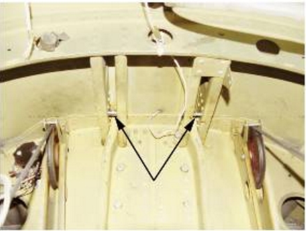 |
Plates through which the bolts are installed, are riveted in place on each channel and the rivet locations are uniform for all four plates. The actuator attachment bolts are shown installed in each of the paired channel assemblies.
The Beechcraft Illustrated Parts Manual P/N 99-590014F5, Figures 103 and 131 illustrate the airframe structure and figure 364 illustrates the trim actuator unit..
The mounting lugs at the top of the stabilizer trim actuator hold the actuator in place. Each mounting lug is fitted with a pivot-ball bearing assembly. When installed correctly, the bolts seen in Figure 1 are inserted through these pivot-ball assemblies to attach the actuator to the airframe.
Installation of the actuator requires the installer to hold the actuator in position with the mounting lugs in place between their respective channel assemblies. The installer is on his knees, leaned forward and holding the actuator (approximately 10 lbs) in place and ahead of him. The mounting lugs are hidden from view by the channels and the bolts are installed by feel.
Post-accident inspection revealed worn rivets and marks on the actuator lugs indicating that the actuator lugs had been installed forward of the normal mounting position with both of the actuator mount swivel balls against the upper edge of their respective mounting-plate rivets. While the mounting lugs were positioned in this manner, the mounting bolts were installed by-feel, but they passed behind the mounting lugs, trapping them between the rivets and the shank of each bolt. With the installation of the first bolt, the weight of the actuator was suspended as if the bolt had gone through the actuator mounting lug assembly. Both mounting lugs are fixed to the actuator and when the first mounting lug is improperly placed, the second lug is positioned in the same manner. When the second attachment bolt was installed, that bolt passed behind its attachment lug trapping it in the same manner as the first attachment lug.
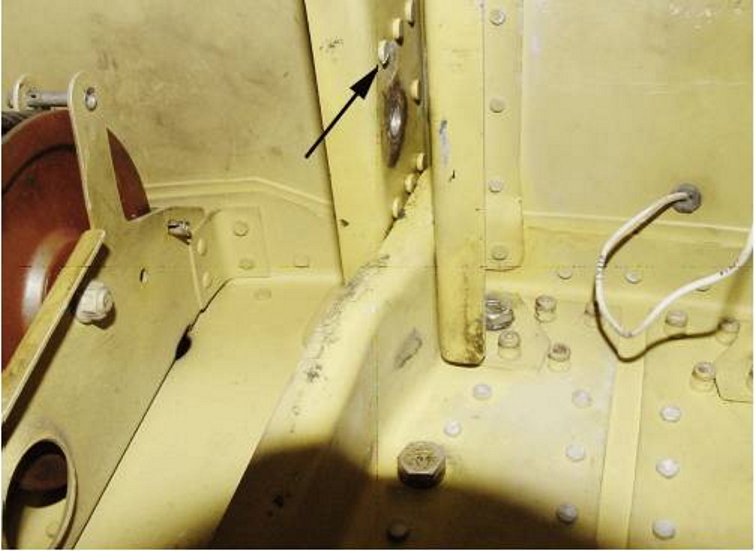
Figure 3
Figure 3 shows worn rivet ahead of the mounting hole.
When a dual inspection of the installation was conducted, the bolts were confirmed to be installed through the holes in their airframe channels and the appropriate washers and self-locking nuts were in place. The proximity to a bulkhead, the airframe channel assemblies on either side of the mounting lugs, and the body of the trim actuator precluded access to the rear of the channels for inspection using an inspection mirror. The non-conforming installation was not detected.
This investigation is ongoing. Accordingly we cannot at this time draw conclusions or make findings as to the causes of the occurrence, as that is a function of the Board, once the field phase of the investigation is complete.
 |
|
 |